
A machine designer once could not work out why two seemingly identical cylinders, same bore, same rod, same stroke, behaved so differently in service, with one wearing its rod and seals far faster than the other. The difference was not in the cylinders but in how they were mounted. One was mounted in a way that let it self-align with its load, and the other was rigidly mounted in a way that forced side loads into the rod every time the machine flexed. The mounting style, often treated as an afterthought, was determining the loads the rod and bore actually saw. Mounting is not just how you attach a cylinder; it is a structural decision.
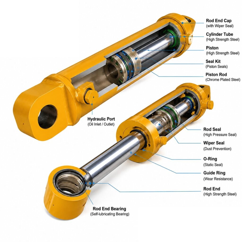
How a hydraulic cylinder is mounted determines how forces are transmitted between the cylinder and the machine, and therefore how the rod, bore, seals, and bearings are loaded. The wrong mounting for an application introduces side loads, misalignment, and buckling risk that no amount of rod quality can fully overcome, while the right mounting lets the cylinder do its job with the loads it was designed for. For engineers, understanding mounting styles and their effect on rod loading is essential to durable cylinder installations.
Why mounting style matters
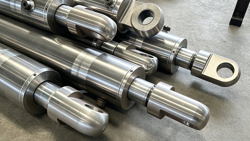
A cylinder ideally sees only axial load, pushing and pulling along its centreline, and the rod, bore, and seals are designed for that. Mounting style matters because it determines whether the real installation actually delivers axial load or whether it forces transverse, bending, or misalignment loads into the cylinder. A mounting that keeps the load aligned with the cylinder axis protects the rod and seals, while one that allows or forces misalignment loads them in ways they were not designed for, causing the accelerated wear the puzzled designer saw.
The core distinction is between mountings that allow the cylinder to pivot and self-align and those that hold it rigidly. Pivoting mountings let the cylinder swing to follow a moving or slightly misaligned load, keeping the force axial even as geometry changes, which suits applications where the load moves through an arc or where perfect alignment cannot be guaranteed. Rigid mountings fix the cylinder in position, which suits applications with well-guided, purely axial loads but which transmit any misalignment or side load directly into the cylinder.
Choosing the wrong category is a common and costly error. Using a rigid mounting where the load moves or the structure flexes forces side loads into the rod and bore, while using a pivoting mounting where the application needs a fixed, guided line of action can allow unwanted movement. Matching the mounting category to how the load actually behaves is the first and most important mounting decision, and it directly determines the loads the rod will carry.
Pivoting mountings: clevis and trunnion
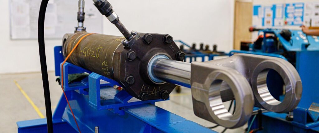
Clevis mountings, at the cap end and often paired with a pivoting rod-end connection, let the whole cylinder swing in a plane about a pin. This allows the cylinder to follow a load that moves through an arc, such as driving a pivoting lever or boom, keeping the force along the cylinder axis as the geometry changes. Because it self-aligns in its plane of motion, a clevis mount avoids forcing side loads into the rod as long as the motion stays in that plane and the pins are properly aligned.
The caution with clevis mounts is out-of-plane loading. A clevis allows pivoting in one plane, so any side load perpendicular to that plane is not accommodated and goes into the cylinder, and any twist or misalignment across the pins introduces loads. Clevis mounts also work with the rod end connection to define the pivot geometry, and both ends must align so the cylinder swings freely without binding. Within their plane of motion and with good pin alignment, clevis mounts are excellent for arcing loads; outside it, they offer no protection.
Trunnion mountings support the cylinder on pivots, or trunnions, projecting from its sides, allowing it to pivot about that axis, and can be located at the cap, the head, or intermediate along the barrel. Like clevis mounts, trunnions let the cylinder swing to follow a moving load, and the position of the trunnions affects the effective column length and how the cylinder is supported. Trunnions carry significant loads through the pivot bearings, so those bearings and their alignment are important, and the trunnion position must be chosen considering both the pivoting motion and the buckling behaviour of the extended cylinder.
Rigid mountings: flange and foot
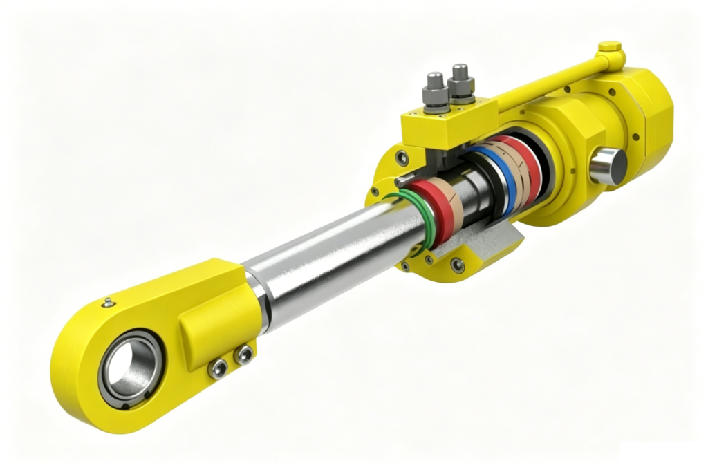
Flange mountings attach the cylinder rigidly through a flange at the head or cap end, bolting it solidly to the machine structure. This gives a fixed, precise line of action and is well suited to applications where the load is guided and purely axial, such as a press or a well-supported linear actuator. A flange mount provides a strong, rigid connection and, when the load is truly axial and aligned, keeps the cylinder loaded as designed. Head-end and cap-end flange mounts differ in how they handle tension and compression loads, and the choice depends on the direction of the main load.
The requirement and risk with rigid flange mounts is alignment, because a rigid mount transmits any misalignment straight into the cylinder. If the cylinder axis is not precisely aligned with the load’s line of motion, or if the machine structure flexes under load, a flange mount forces the resulting side loads into the rod and bore rather than accommodating them by pivoting. This is why rigid mounts demand careful alignment and a rigid, well-guided load path, and why using them with a moving or poorly aligned load causes the side-load wear the designer experienced.
Foot or side-lug mountings bolt the cylinder to a surface along its base, another form of rigid mounting, and they carry their own considerations. Because the mounting surface is offset from the cylinder centreline, foot mounts can create a turning moment under load that tends to lift or rock the cylinder, so they must be well secured and sometimes located to react the load properly. Like flange mounts, foot mounts suit fixed, aligned, guided loads and require good alignment to avoid inducing side loads. The common thread among rigid mounts is that they reward precise alignment and punish misalignment.
Choosing the mounting for the load
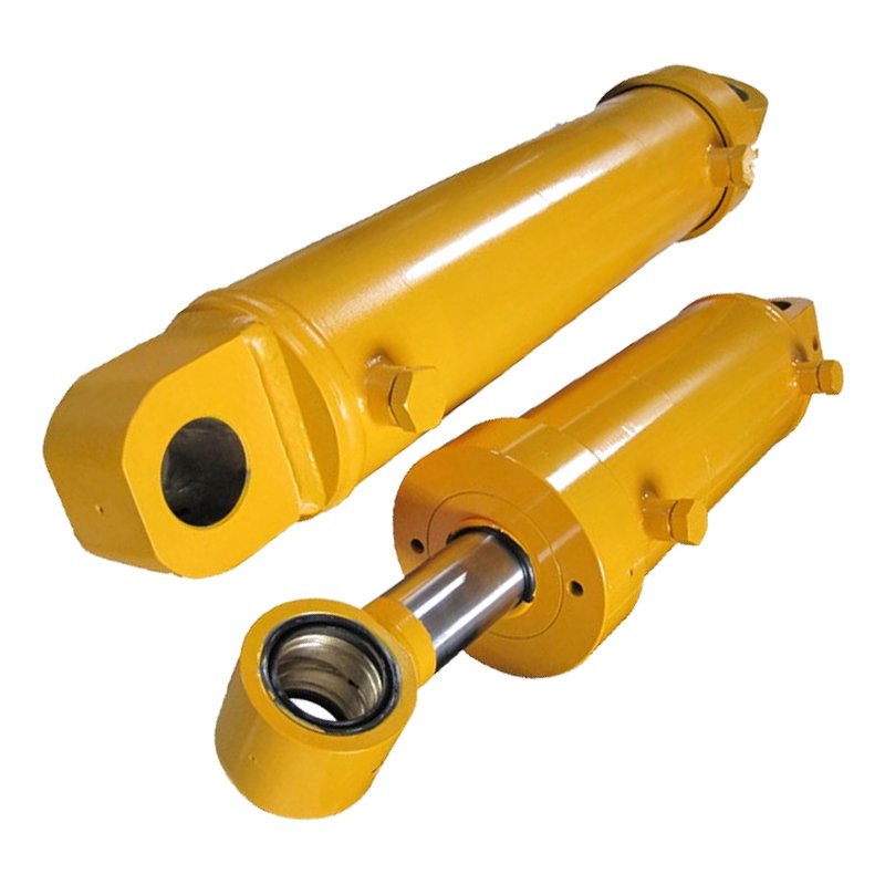
Selecting a mounting style starts with understanding how the load moves and how well it is aligned and guided. If the load moves through an arc or the alignment cannot be guaranteed, a pivoting mount, clevis or trunnion, lets the cylinder self-align and keeps the load axial, protecting the rod and seals. If the load is purely axial, well-guided, and precisely alignable, a rigid mount, flange or foot, gives a fixed, strong line of action. Matching the mounting to the load’s real behaviour is the essence of the decision.
Mounting choice also interacts with rod loading and buckling, which ties it to rod and cylinder sizing. The mounting and its alignment determine the side loads the rod bushing and bore must react, and, as with column stability, the end conditions the mounting creates affect the effective length and buckling capacity of the extended cylinder. So mounting is not independent of rod sizing and gland design; a mounting that induces side loads demands more of the rod bearing, and one that creates a long effective column demands more of the rod diameter. The mounting, rod, and gland should be considered together.
The practical guidance is to treat mounting as a structural design decision made alongside the cylinder specification, not an afterthought bolted on at installation. Consider how the load moves, how precisely the cylinder can be aligned, how the structure flexes under load, and how the mounting affects side loading and buckling, then choose the style that keeps the cylinder loaded as it was designed to be. Get the mounting right, and identical cylinders behave identically well; get it wrong, and even a good cylinder wears out fast, exactly as the designer discovered.
Related Reading
- Chrome Plated Rod for Truck-Mounted and Crawler Cranes: Long-Stroke Straightness and Bending Resistance: https://eastai-tech.com/chrome-plated-rod-for-truck-mounted-and-crawler-cranes-long-stroke-straightness-and-bending-resistance/
- Honed Tube for Crane and Lifting Equipment: Long-Stroke Straightness Requirements: https://eastai-tech.com/honed-tube-for-crane-and-lifting-equipment-long-stroke-straightness-requirements/
Mount It Right, and the Rod Lasts
The best rod and bore still wear fast under a bad mounting. EAST AI has supplied the honed tube and chrome rod behind well-mounted cylinders since 2006, and we help engineers match components to the mounting and the loads it creates.
What we offer:
- Chrome plated rod sized and finished for the side loads your mounting allows
- Honed tube with the bore quality and straightness for aligned operation
- Technical support on mounting effects, rod loading, and buckling
- Consistent components so your installation performs as designed
Tell us your mounting and load path, and we will help you spec rod and tube. Email: marketdi@east-ai.cn | Phone: +86 13382202696 Address: No. 108, Lunan Road, Wuxi, Jiangsu, China.
Written by Alex, Production Engineer at EAST AI