
Written by Alex, Production Engineer at EAST AI
A customer once specified a long-stroke cylinder with a rod diameter chosen purely from the pressure and the required push force, and was baffled when the rod bent under a load well within its calculated compressive strength. The steel had ample strength for the force, the chrome was intact, and nothing had been overloaded in the ordinary sense, yet the rod had failed by bowing sideways rather than by crushing. The failure mode was column buckling, an instability that depends on the rod’s length as much as its strength, and it is one of the most commonly overlooked calculations in cylinder design.
Column buckling matters because a long, slender rod under compression can become unstable and deflect sideways long before the material reaches its compressive yield, and the longer the stroke the more severe the risk. For the engineers sizing hydraulic cylinders, buckling is a distinct failure mode from pressure containment or material strength, governed by the geometry of the rod and the way the cylinder is mounted, and it frequently sets the rod diameter for long-stroke applications. Understanding the Euler buckling relationship, the influence of mounting, and the role of the stop tube is essential to sizing a rod that stays straight under load.
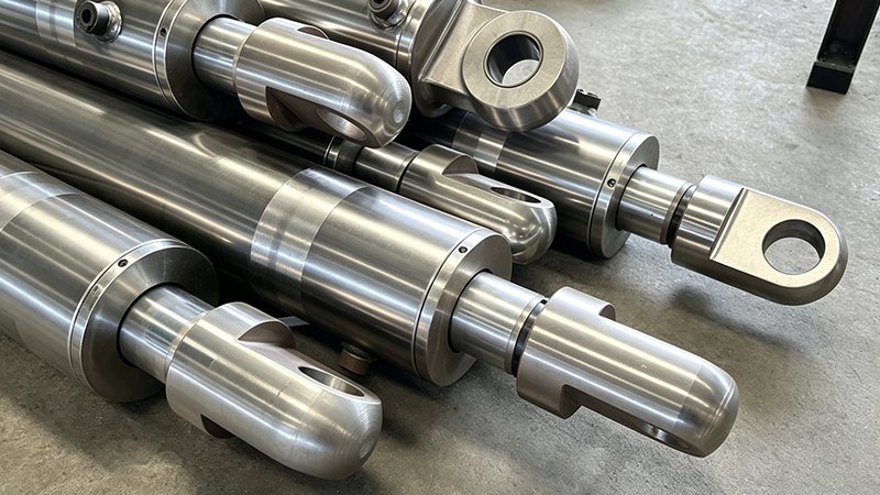
Why Buckling Is a Stability Problem, Not a Strength Problem
Column buckling is fundamentally different from the strength failures that dominate most component sizing, because it is a question of stability rather than of stress reaching a limit. A slender column under compressive load remains straight only while that load is below a critical value, and once the load exceeds the critical buckling load the column suddenly deflects laterally and collapses, even though the material stress at the moment of instability may be well below yield. This is why a rod can buckle under a force its material could easily carry in pure compression, and why checking material strength alone gives a false sense of security.
The critical distinction is that buckling depends strongly on the length of the column, whereas material strength does not, so a rod diameter that is perfectly adequate at a short stroke can be dangerously slender at a long one. As stroke increases, the unsupported length of the rod grows, and the critical buckling load falls rapidly, which is why long-stroke cylinders are where buckling most often governs the design. Recognizing buckling as a length-dependent stability problem, separate from the strength calculation, is the first step toward sizing rods that do not fail by bowing.
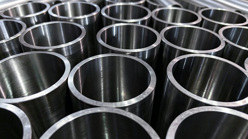
The Euler Buckling Relationship
The classical description of column buckling is the Euler formula, which gives the critical buckling load as proportional to the material’s elastic modulus and the cross-section’s moment of inertia, divided by the square of the effective column length. Two features of this relationship dominate rod sizing. First, the critical load depends on the square of the length, so doubling the effective length quarters the buckling capacity, which is why long strokes are so punishing. Second, the moment of inertia of a round rod scales with the fourth power of its diameter, so modest increases in rod diameter produce large increases in buckling resistance.
These two dependencies together explain why rod sizing for buckling is so sensitive to geometry and why the lever an engineer has is primarily the rod diameter. Because buckling capacity rises with the fourth power of diameter but falls with the square of length, a long-stroke cylinder often needs a rod substantially larger than the pressure and force alone would suggest, purely to remain stable. Running the Euler calculation, rather than sizing the rod from force alone, is what reveals the diameter the stroke actually demands, and it frequently surprises engineers who have only ever sized short-stroke cylinders where buckling never governed.
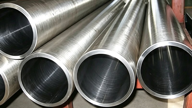
Mounting and the Effective Length Factor
The effective length in the Euler relationship is not simply the physical stroke, because how the cylinder is mounted at each end changes the buckling behavior, and this is captured by an effective length factor that multiplies the actual length. A cylinder rigidly fixed at both ends resists buckling far better than one that is pinned or free to pivot, and a cylinder mounted so that one end is effectively free is the most vulnerable of all. The mounting configuration can change the effective length by a factor of two or more, which through the square relationship changes the buckling capacity by a factor of four or more.
For the design engineer this means the mounting arrangement is not just a mechanical interface detail but a first-order input to the buckling calculation, and the same rod and stroke can be safe in one mounting and unstable in another. Trunnion, clevis, flange, and foot mountings each impose different end conditions and therefore different effective length factors, and the calculation must use the factor appropriate to the actual installation. Ignoring the mounting and assuming a favorable end condition is a common route to an under-sized rod, so a rigorous buckling check always begins with an honest assessment of how the cylinder is truly constrained at each end.
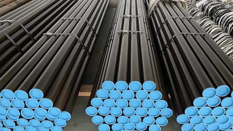
When a Stop Tube Becomes Necessary
As a cylinder extends toward full stroke, the distance between the piston bearing in the bore and the rod bearing in the gland reaches its maximum, and at full extension this bearing spread is at its smallest relative to the extended length, which worsens the effective loading and the side-load reaction on the bearings. A stop tube is a spacer fitted to keep the piston and gland bearings from approaching too closely at full extension, preserving a minimum bearing separation that reduces the bearing loads and improves the effective stability of the fully extended rod. For long-stroke cylinders, a stop tube is often the difference between a stable design and one that overloads its bearings and invites buckling near full extension.
The stop tube works by increasing the minimum distance between the two bearing points, which lowers the reaction forces those bearings must carry for a given side load and improves the buckling behavior of the extended assembly. It does cost stroke length for a given overall cylinder length, which is why it is specified deliberately when the stroke-to-bore ratio and the buckling analysis call for it rather than added by default. Knowing when a stop tube is required, and sizing it correctly, is part of the buckling-aware design of any long-stroke cylinder, and it works together with the rod diameter selection to keep the extended rod stable.
Sizing the Rod With Buckling in Mind
The disciplined design process sizes the rod against both strength and buckling and takes the larger of the two required diameters, which for long-stroke cylinders is very often the buckling requirement rather than the strength one. The engineer establishes the compressive load, determines the effective length from the stroke and the mounting end conditions, applies the Euler relationship with an appropriate safety factor against the critical load, and checks whether a stop tube is needed to preserve bearing separation at full extension. The resulting rod diameter is then the base for the chrome plating and the tolerance specification, completing a rod that is both structurally and dimensionally correct.
For the customer whose long-stroke rod bent under a modest load, the resolution was to re-size the rod diameter against the Euler buckling load for the actual mounting, which called for a larger diameter than the force alone had suggested, and to add a stop tube to preserve bearing separation at full stroke. The rod stopped bowing because the design finally addressed the instability that had always been the real failure mode. That is the essential lesson of column buckling: strength keeps a rod from crushing, but only a buckling calculation keeps a long rod from bowing, and a cylinder design that skips it is trusting to luck on the very failure mode that long strokes make most likely.
Related Reading
- Chrome Plated Rod for Truck-Mounted and Crawler Cranes: Long-Stroke Straightness and Bending Resistance
- Honed Tube for Crane and Lifting Equipment: Long-Stroke Straightness Requirements
- Chrome Plated Rod for Wind Turbine Pitch and Yaw Cylinders: Fatigue Life Under Continuous Micro-Cycling
Size Long-Stroke Rods Against Buckling, Not Just Force
A rod with ample compressive strength can still bow sideways under a modest load if its stroke and mounting were never checked against column buckling. At EAST AI we size long-stroke cylinder rods against the Euler buckling load for your actual mounting end conditions, advise when a stop tube is required, and supply the chrome plated rod at the diameter your stability calculation truly demands.
What We Offer
- Rod diameter sized against both compressive strength and Euler column buckling
- Effective-length analysis matched to your trunnion, clevis, flange or foot mounting
- Stop-tube guidance to preserve bearing separation and stability at full extension
- Chrome plated rod in CK45, 42CrMo and 20MnV6 supplied to the buckling-driven diameter