
A mobile equipment manufacturer once fielded repeated complaints about premature wear at a cylinder’s clevis pin, replacing bushings far more often than the cylinder’s hydraulic components themselves ever needed attention. The honed tube and chrome plated rod inside the cylinder were performing exactly as specified. The wear problem lived entirely at the mounting interface, where the clevis design transmitted the full working load through a pin and bushing arrangement that had not been sized or lubricated adequately for the actual side load and misalignment the application imposed.
This article is for equipment designers and cylinder specifiers, and it explains how trunnion and clevis mounting arrangements carry load differently, how each affects pin and bushing wear, and what to check when a mounting-related wear problem keeps recurring independent of the cylinder’s internal condition.
Two Different Ways to Mount a Cylinder’s Ends
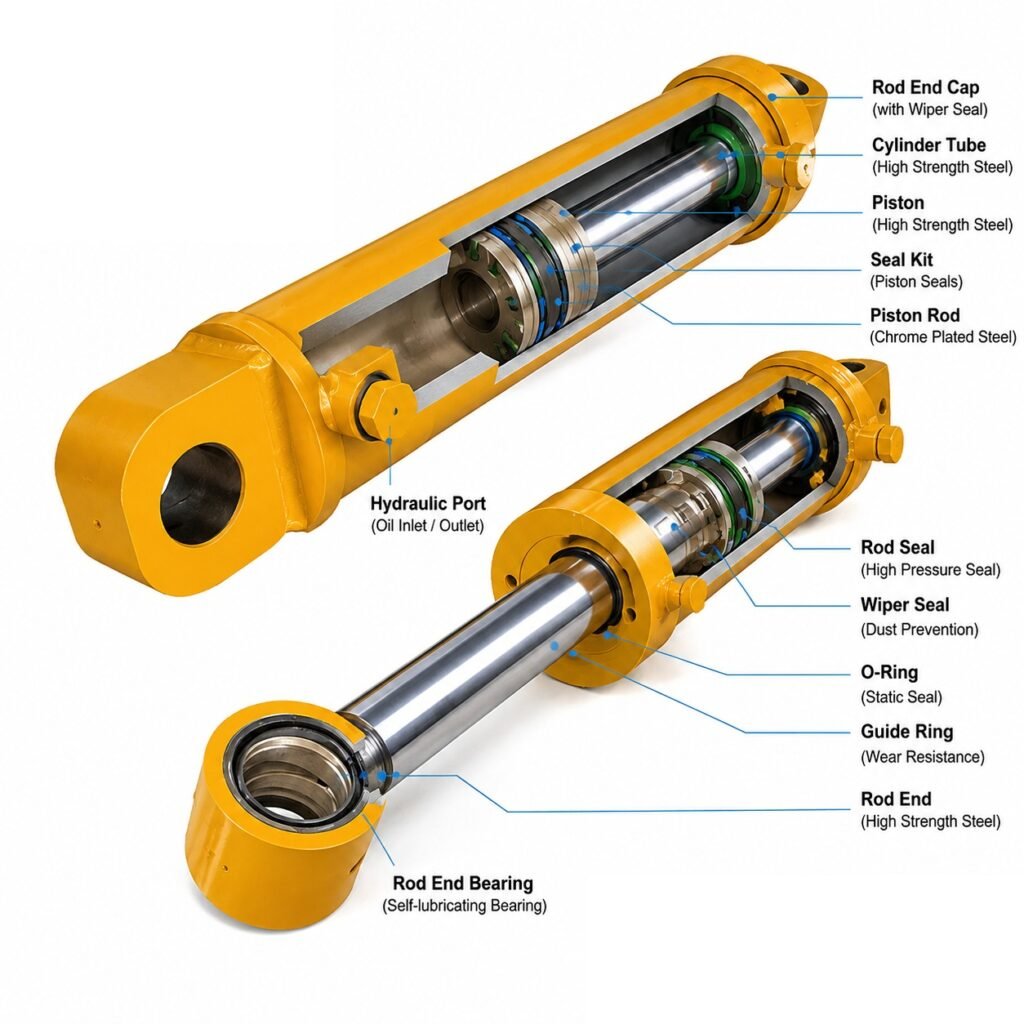
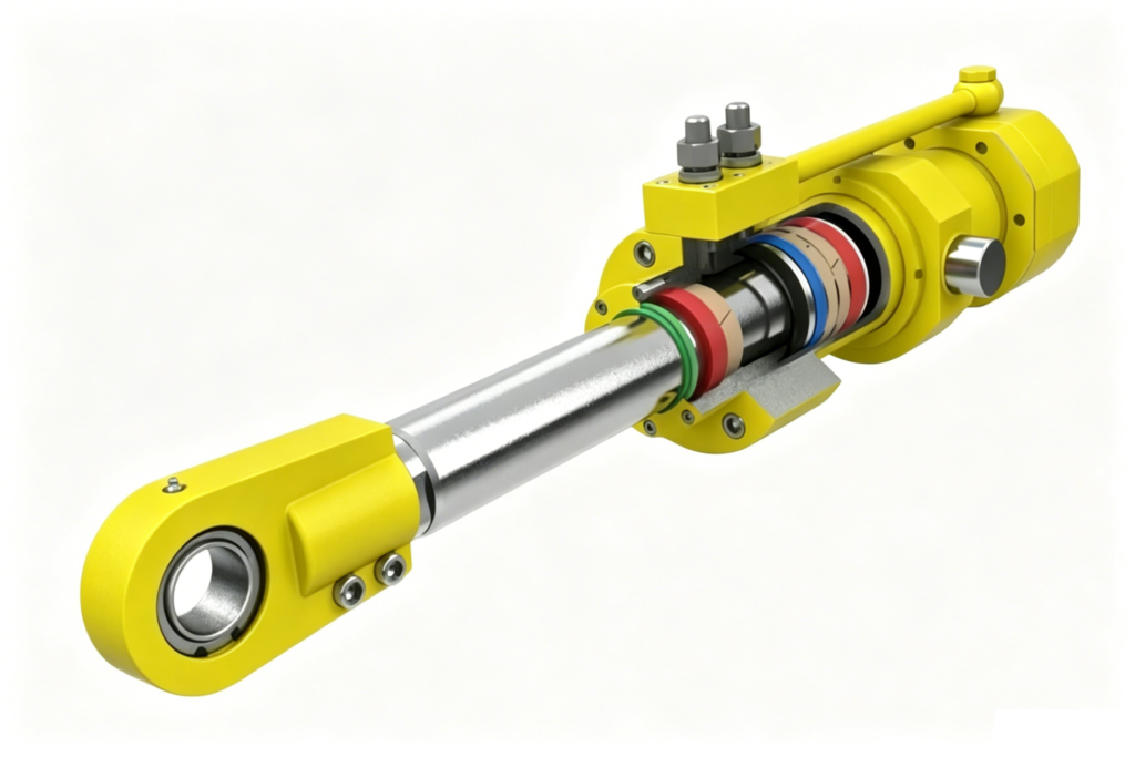
A clevis mount connects the cylinder end through a pin passing through a lug and a mating bracket, allowing rotation in one plane and commonly used at both the cylinder’s base and rod ends in applications requiring the cylinder to pivot as the mechanism moves, such as excavator and loader linkages. A trunnion mount supports the cylinder on a pair of pins projecting from the cylinder body itself, typically positioned to allow the cylinder to pivot while placing the mounting load path through the body rather than through end-mounted lugs. Each arrangement distributes load, side force, and misalignment differently, with direct consequences for pin and bushing wear.
Why Clevis Pins Wear Where Trunnion Mounts Might Not
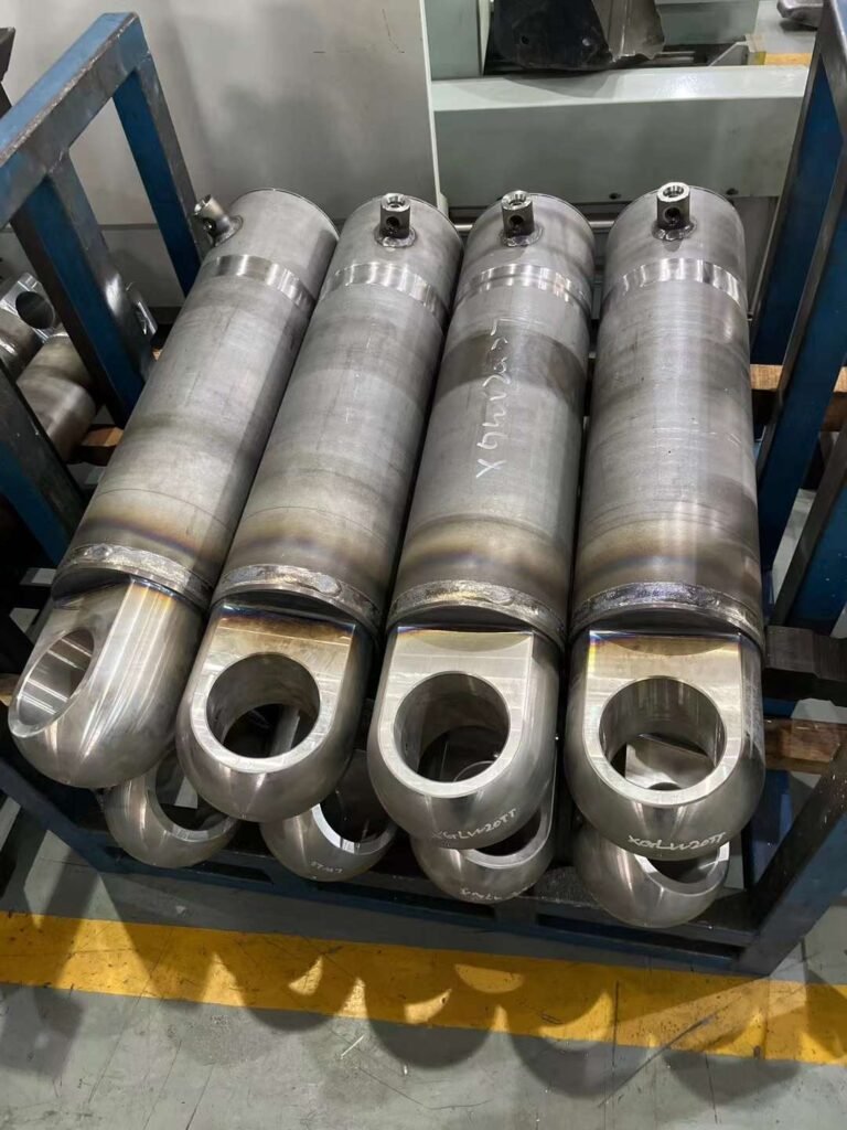
A clevis connection concentrates load transfer through a relatively small pin and bushing contact area, and if the application imposes side load or angular misalignment beyond what the clevis geometry comfortably accommodates, that load concentrates further onto a smaller effective contact area within the bushing, accelerating wear at that specific location. A trunnion mount, positioned closer to the cylinder’s own center of mass and often supporting a different load distribution, can be less sensitive to certain misalignment conditions depending on the specific application geometry, though it introduces its own considerations around bending load on the trunnion pins themselves.
Sizing Pins and Bushings for the Actual Load Path
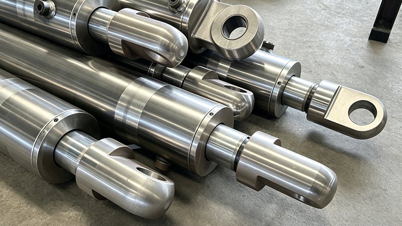
The pin and bushing size at a clevis or trunnion connection should be selected based on the actual calculated bearing load, including any side load and misalignment the application genuinely imposes, not simply scaled from a similar-looking cylinder on a different machine. Undersized pins and bushings concentrate bearing stress into a smaller contact area, accelerating wear regardless of how well the cylinder’s internal components perform, which is exactly the gap that produced the mounting-driven wear complaints in the example above.
Lubrication and Maintenance at the Mounting Interface
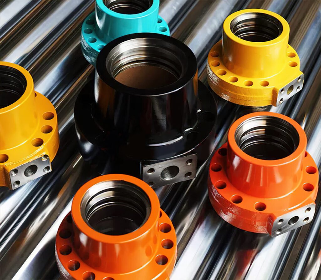
Pin and bushing wear is also strongly influenced by lubrication practice, and a mounting interface that is difficult to access for routine greasing, or simply gets missed in a maintenance schedule focused on more visible hydraulic components, will wear faster than an identical interface that receives regular lubrication. Specifying accessible grease points and building pin and bushing lubrication explicitly into a maintenance schedule, rather than assuming it happens as part of general equipment care, protects an otherwise well-sized mounting arrangement from avoidable wear.
Separating Mounting Wear From Cylinder Wear
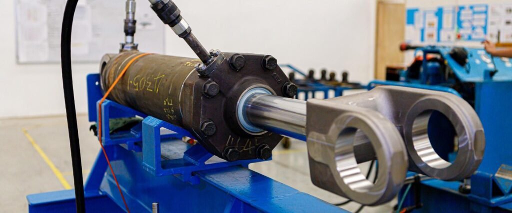
For equipment builders and service technicians diagnosing a wear complaint, distinguishing between mounting-interface wear and internal cylinder wear early in the investigation avoids wasted effort rebuilding a cylinder’s hydraulic components when the actual problem lives at the pin and bushing. A quick check of pin and bushing clearance, independent of any internal cylinder disassembly, often resolves this question faster than assuming the complaint must originate from the honed tube or chrome plated rod inside.
Specifying Mounting Arrangements Deliberately
The practical lesson for designers is to treat clevis and trunnion mounting as a genuine engineering decision, sized for the application’s actual load path, side load, and misalignment, rather than a default carried forward from a previous design without reconsideration. Getting this right protects the significant investment made in a correctly specified cylinder from being undermined by a mounting interface that was never properly matched to the load it would actually carry.
Related Reading
- Hydraulic Cylinder Rod Buckling: Euler Column Strength and Stroke Length Limits
- Stop Tube in Long-Stroke Hydraulic Cylinders: Why It Extends Life
- Chrome Plated Rod Base Steel: Carbon Steel Core vs Alloy Steel Core
The Wear Problem May Not Be Inside the Cylinder at All
A clevis or trunnion mount that is undersized or poorly lubricated for the actual load path wears at the pin and bushing while the cylinder’s internal components perform fine. Size mounting hardware for real bearing load, build in accessible lubrication, and check the mounting interface before assuming the cylinder itself is at fault.
What We Offer
- Chrome plated rod and honed tube supporting cylinder designs with correctly specified mounting interfaces
- Technical guidance on load path considerations for clevis and trunnion mounting decisions
- Base steel and heat treatment options supporting robust pin and bushing performance
- Full material traceability for equipment designers and cylinder specifiers
Contact EAST AI (eastai-tech.com) Email: marketdi@east-ai.cn Phone: +86 13382202696 Address: No. 108, Lunan Road, Wuxi, Jiangsu, China.
Written by Alex, Production Engineer at EAST AI