
Published: 2026-10-15 | Last Updated: 2026-10-15
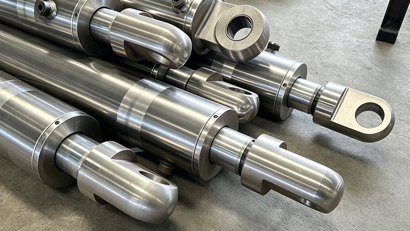
An engineer designing a new cylinder who defaults to whatever rod end configuration appeared on the previous design, without reconsidering whether it actually fits the new application’s mounting and load requirements, is making a decision by inertia rather than by analysis. Rod end configuration — threaded, clevis, eye, or custom machined — determines how the cylinder connects to the load it’s moving, and getting this wrong doesn’t show up as a material defect; it shows up as premature wear at the connection point, or worse, a mounting failure under load. Walking through the actual decision factors, rather than defaulting to a familiar configuration, produces a more reliable connection for the specific application at hand.
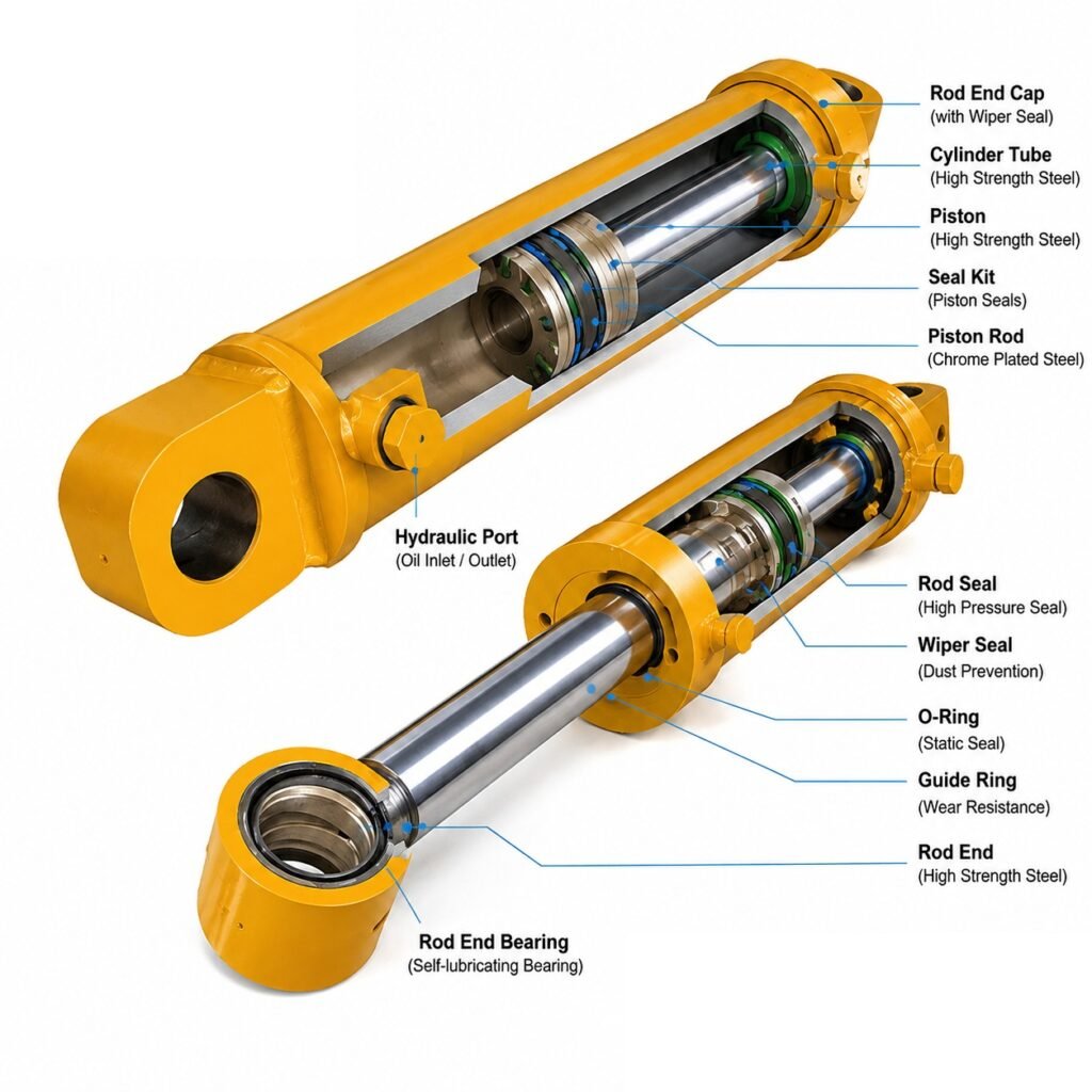
The Main Rod End Configurations and What They’re Suited For
| Configuration | Load Path Characteristic | Best Suited For |
|---|---|---|
| Male threaded | Direct axial connection, compact | Simple axial-load applications, piston-to-rod-end linkages |
| Female threaded | Allows a stud or bolt connection from the mating part | Applications where the mating component carries the threaded stud |
| Clevis | Pivoting connection, accommodates angular movement | Applications where the cylinder’s mounting angle changes during the stroke |
| Eye / spherical bearing | Allows multi-axis articulation | Applications with side load or misalignment during operation |
| Custom machined | Application-specific geometry | Non-standard mounting interfaces or proprietary equipment designs |
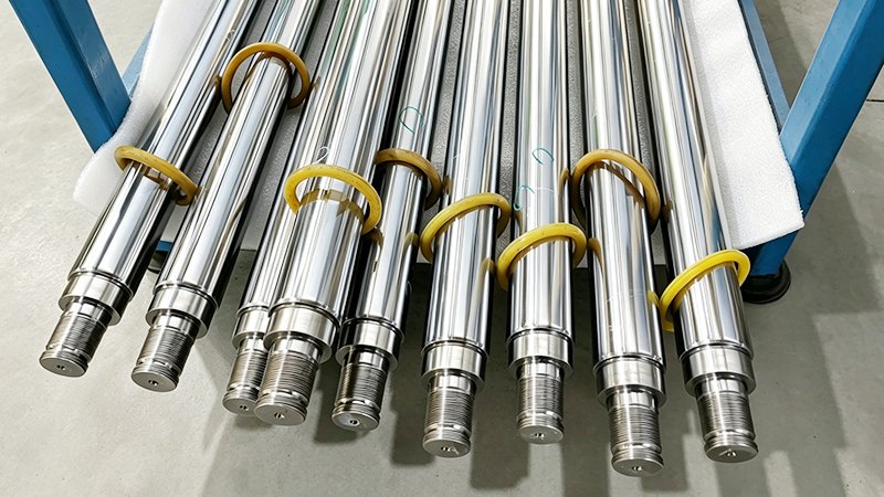
Why Thread Type and Class Matter as Much as the Configuration Choice
Beyond choosing threaded versus clevis versus eye, the specific thread type (metric, UNC, UNF) and tolerance class must match the mating component exactly — a mismatch here causes either a loose connection that works itself free under cyclic load, or a tight connection that galls during assembly. Specifying thread type and class explicitly, rather than assuming “standard thread” is unambiguous, avoids a surprisingly common and entirely avoidable source of field failures.
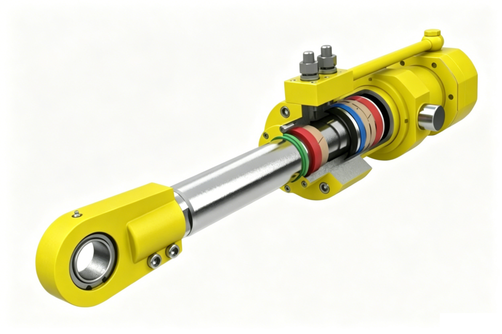
How Side Load Changes the Calculation
Rod end configurations that don’t accommodate angular movement — a simple male threaded connection, for example — perform fine in purely axial-load applications but become a liability in applications where the cylinder’s mounting angle shifts during the stroke, introducing side load the connection wasn’t designed to handle. A clevis or spherical bearing eye configuration, which permits pivoting, is the correct choice specifically because it keeps the load path axial through the rod even as the external mounting geometry changes angle, protecting the rod and its chrome finish from the kind of asymmetric wear that a rigid connection would produce under the same conditions.
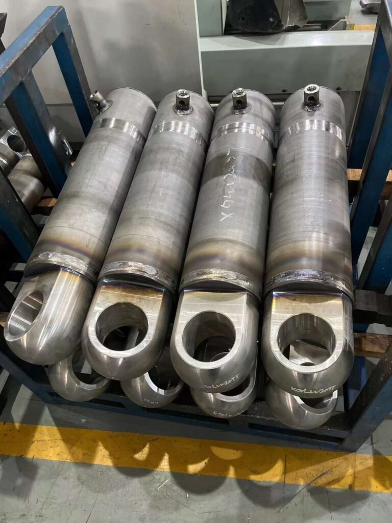
Machining Sequence and Chrome Protection
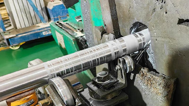
Rod end features — threads, flats, clevis bores — are typically machined either before or after chrome plating depending on the specific feature and the supplier’s process capability, and getting this sequence wrong risks damaging the chrome layer during machining or leaving unplated, corrosion-vulnerable surfaces where protection is actually needed. Confirming with a supplier how a specific end configuration will be sequenced relative to plating, rather than assuming it’s a simple afterthought, protects both the dimensional accuracy of the finished feature and the integrity of the chrome coating around it.
Matching End Configuration to the Rest of the Cylinder Design
Rod end configuration doesn’t exist in isolation — it needs to be considered alongside the cylinder’s overall mounting style (trunnion, clevis-mounted, flange-mounted) and the gland and bearing design, since a mismatch between how the cylinder body mounts and how the rod end connects to the load can introduce exactly the kind of combined stress that neither component was individually designed to handle. Reviewing the full load path from cylinder mount through rod end to the actual load connection, rather than specifying each piece independently, catches these interaction effects before they become field problems.
A Practical Specification Checklist
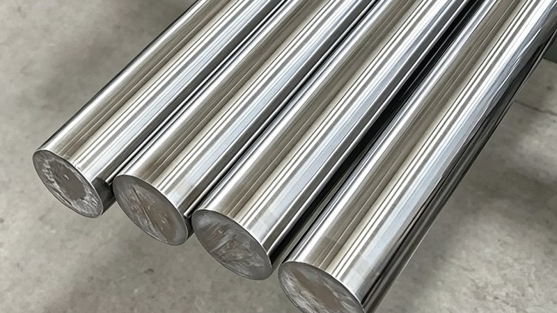
For engineers specifying new chrome plated rod with a particular end configuration, confirming the exact thread type and tolerance class (not just “standard”), communicating whether the application involves any angular movement or side load during the stroke, and discussing machining sequence relative to plating with the supplier covers the main decision points that determine whether the resulting rod end performs reliably over the application’s full service life.
Discuss Rod End Configuration for Your Design
Specifying rod end configuration for a new cylinder design? Talk with our team about matching end configuration to your actual load path and mounting geometry.
Related Reading
- Hydraulic Cylinder Trunnion and Clevis Mounting: Load Path and Pin Wear Considerations
- Hydraulic Cylinder Side Load: Why Guided Load Applications Need Different Rod and Bore Tolerances
- Chrome Plated Rod Thread Rolling vs Cutting: Protecting the Chrome at the Ends
What We Offer
- Full range of rod end configurations including threaded, clevis, eye, and custom machined features
- Machining sequence coordinated with plating process to protect chrome integrity at critical features
- Technical consultation on matching end configuration to actual load path and side-load conditions
- Precise thread type and tolerance class control matched to mating component requirements
Contact EAST AI (eastai-tech.com) Email: marketdi@east-ai.cn Phone: +86 13382202696 Address: No. 108, Lunan Road, Wuxi, Jiangsu, China.
Written by Alex, Production Engineer at EAST AI